Four supported platforms
Hinged floor panels lower around the centre. Perimeter supports carry the deployed floors; their loads and positions need development.
SHEBAN HOMES / VERSION 2
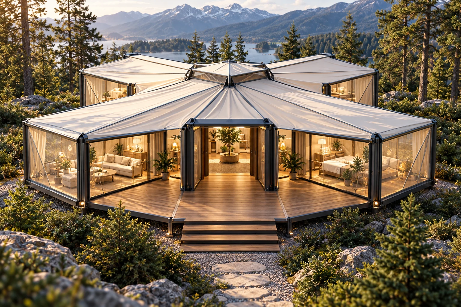
An unfolding pavilion with warm timber underfoot, transparent walls and a light roof that opens towards the trees. Small and enclosed between visits. Open and connected to the landscape when you arrive.
Explore the ten pavilion views ↓Go directly to the patio and flat-pack images ↗
A separate concept developed from your supplied specification sheet. The earlier Compact and Family studies remain available in the original collection.
SHEBAN HOMES / THE ENLARGED STUDY
Open any image to see it larger. These generated design interpretations expand your original sheet; the dimension table and captions identify what remains to be developed.
Appearance interpretation: the cream roof, dark frame and timber finishes develop the source character. This rendering reads as an octagonal pavilion rather than the four-wing cross; it does not represent the stated floor area.
Save image 01 ↓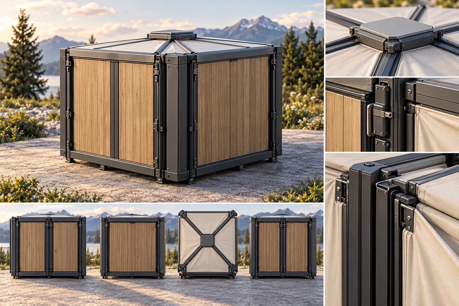
A closed-box study with detail views; the lower strip shows three elevations and a top view. The shallow raised cap differs from the flat transport-cap intention. The source gives a 3.0 × 2.4 × 2.6 m envelope; panel stacking and height remain to be reconciled.
Save image 02 ↓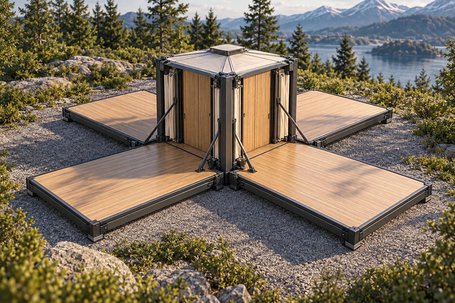
Supported hinged platforms open around the core. These are the source’s four extensions; additional telescoping glide-outs are not established for Version 2.
Save image 03 ↓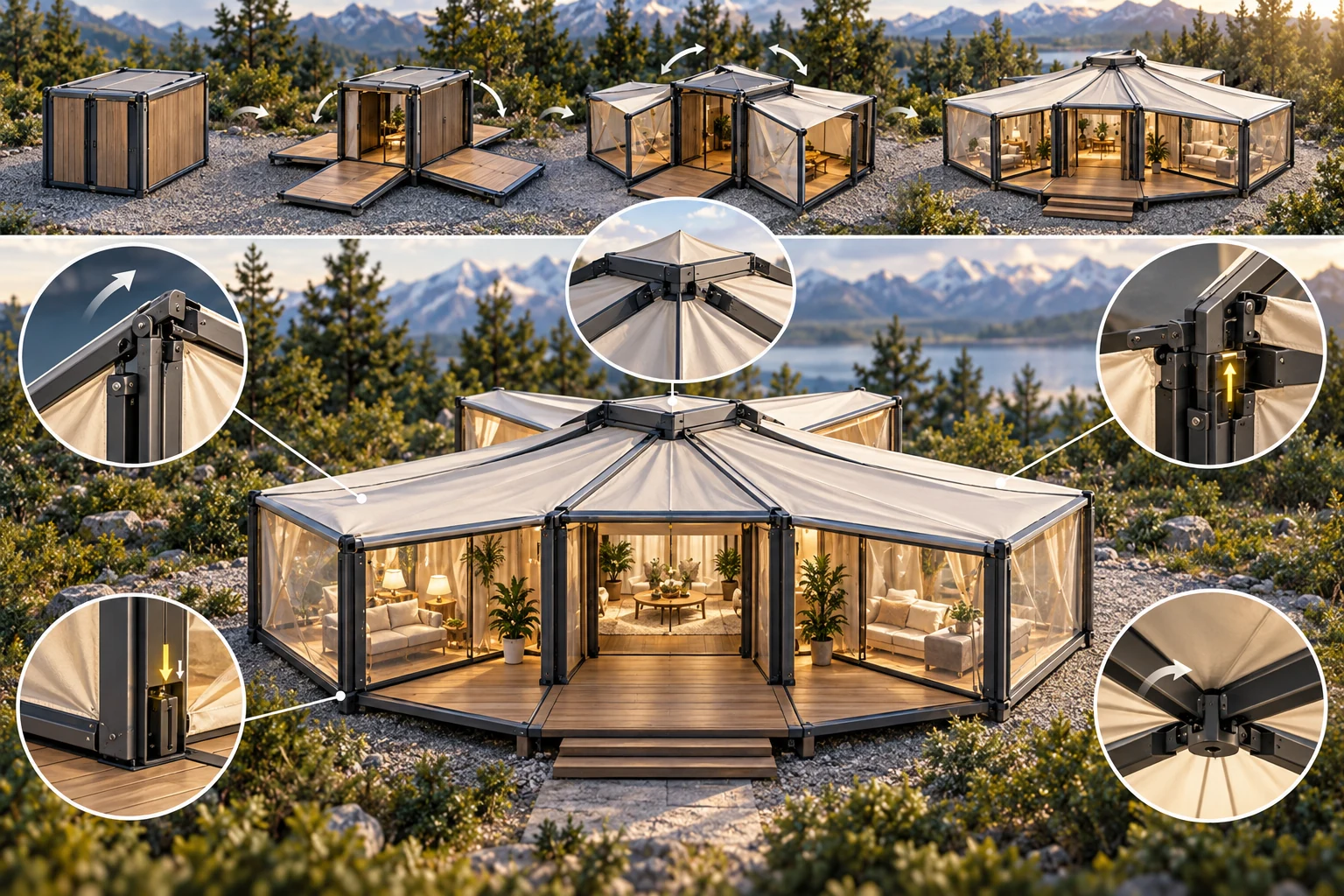
Opening storyboard and proposed joint details. The finished view reads as an octagonal pavilion rather than the four-wing cross; joint locks, pivot clearances and handling order remain to be prototyped.
Save image 04 ↓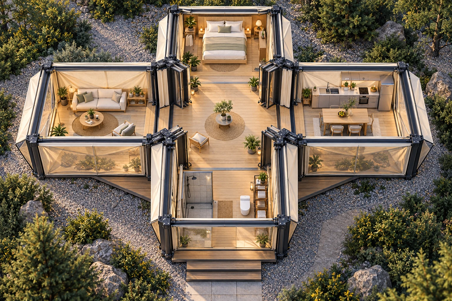
A proposed cross-shaped furnished cutaway. The pictured bathroom occupies the entrance route and lacks a resolved privacy partition; its position must change in the coordinated plan. Wing ends appear chamfered rather than square; the small corner decks are not included in the floor-area calculation.
Save image 05 ↓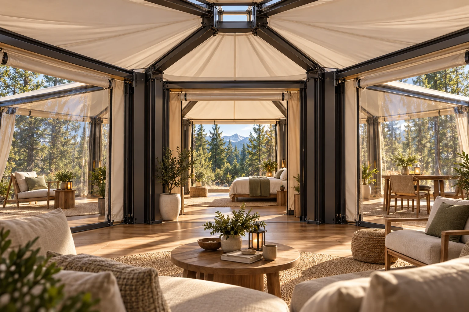
Transparent panels bring the forest into the room. The radial, multi-bay roof differs from the four-wing cross. Furnishings and equipment are illustrative choices, not a confirmed included package.
Save image 06 ↓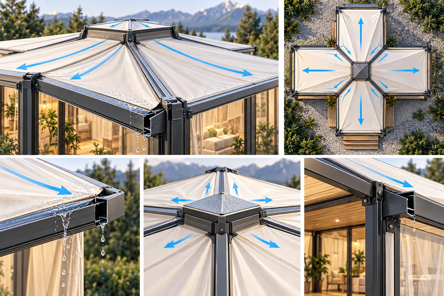
The large arrows illustrate the intended outward rain path. Some small arrows and gutter-junction details are ambiguous; controlled outlets and a continuous roof seal require a coordinated drainage detail.
Save image 07 ↓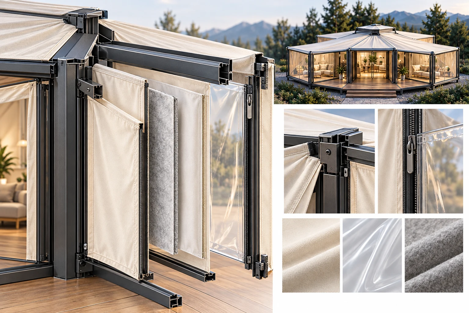
Frame, fabric, optional liner and transparent window connection. The pictured swatches illustrate fabric, clear window material and insulation, not verified PVC, PVDF or PTFE products. The pavilion inset reads as an octagonal pavilion; the four-wing cross plan governs.
Save image 08 ↓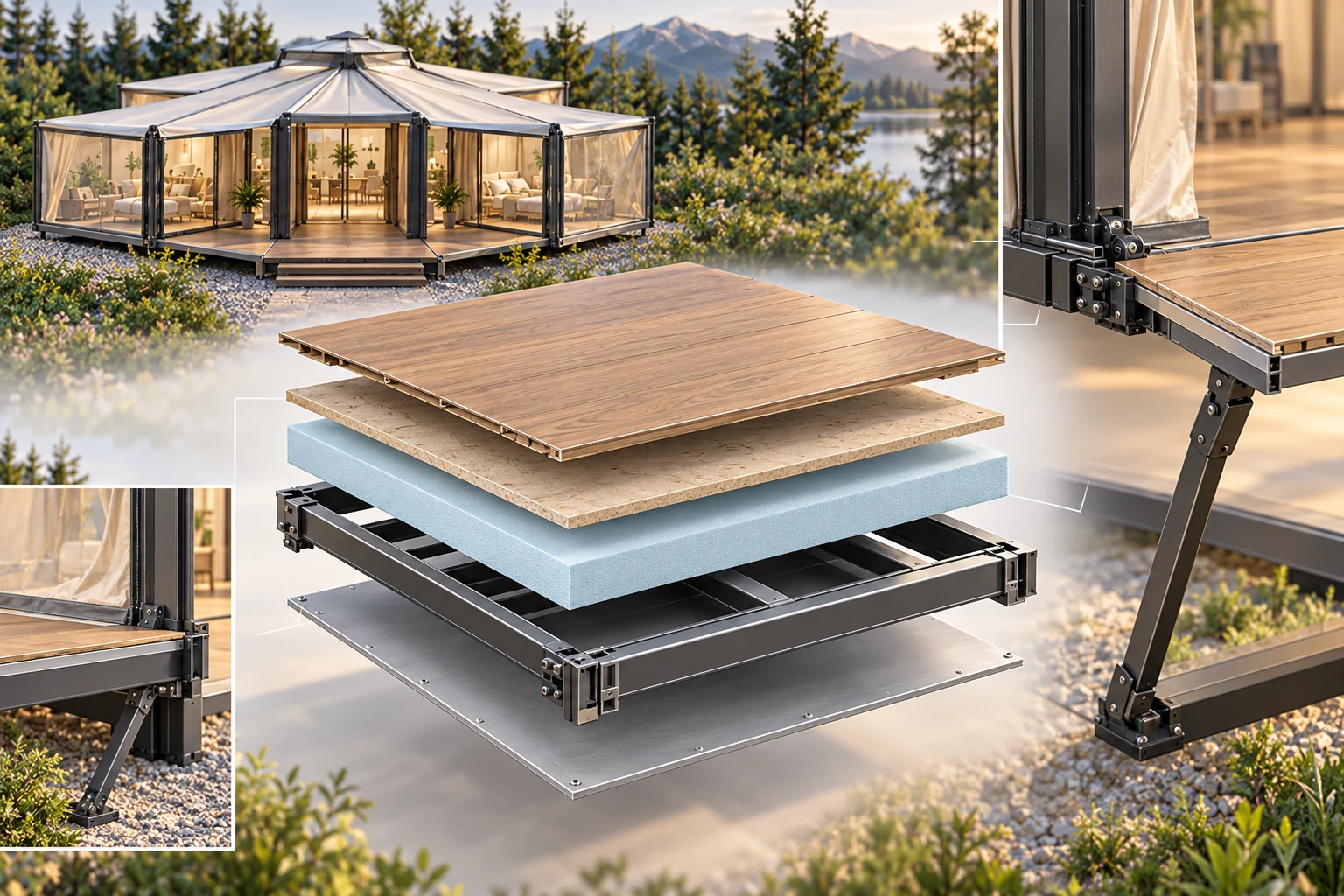
Wood-look surface, structural board, insulation, aluminium frame and bottom panel. Layer thicknesses and structural connections have not been sized. The background reads as an octagonal pavilion; the four-wing cross plan governs.
Save image 09 ↓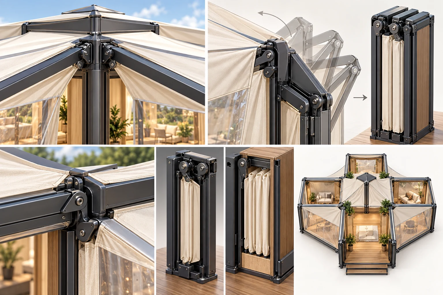
An articulated-rib and storage interpretation, with an appearance inset whose massing differs from the four-wing cross. A physical prototype must establish pivot paths, locks and available storage volume.
Save image 10 ↓THE STARTING POINT
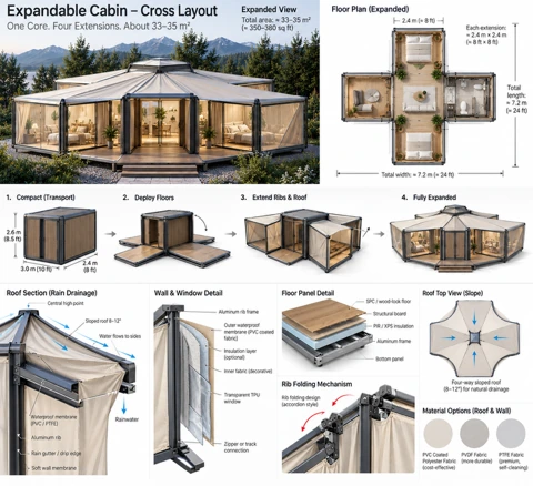
The defining features are the cross-shaped floor, four hinged extensions, accordion-style ribs, outward-draining membrane roof and transparent window walls. This is a new architecture and mechanism study, with its own dimensions.
THE VERSION 2 SYSTEM
Hinged floor panels lower around the centre. Perimeter supports carry the deployed floors; their loads and positions need development.
The source shows a central high point and four-way slopes towards the outside edges, with gutters or drip edges at the perimeter.
Dark frames hold fabric wall panels and transparent TPU windows, with zipper or track connections and an optional insulation layer.
SOURCE DIMENSIONS / TO RECONCILE
| Item | Source value |
|---|---|
| Compact transport box | 3.0 × 2.4 × 2.6 m |
| Each extension | About 2.4 × 2.4 m |
| Expanded overall extent | About 7.2 × 7.2 m |
| Stated expanded floor area | About 33–35 m² (sheet approximation: 350–380 sq. ft.) |
A square 2.4 m core plus four 2.4 m square wings gives 28.8 m² (about 310 sq. ft.). Using a 3.0 × 2.4 m core with those wings gives 30.24 m² (about 326 sq. ft.) and a different overall extent. The sheet’s 33–35 m² area is a target to reconcile, not a confirmed floor plan.
LOOK CLOSER / THE LAYERS
A waterproof outer membrane spans the aluminium ribs. The source suggests an approximately 8–12° four-way slope, carrying rain from the high centre towards a gutter or drip edge. The foldable connection at the core remains a detail to develop.
An outer waterproof fabric, optional insulation and inner fabric liner sit alongside transparent TPU window panels. Zipper or track connections are the source’s proposed way to connect and replace sections.
Five layers are shown: SPC or wood-look finish, structural board, PIR or XPS insulation, an aluminium frame and a protective bottom panel. Thicknesses, hinge connections and support spacing remain to be sized.
| Source option | What to develop with a supplier |
|---|---|
| PVC-coated polyester fabric | Weight, seam method, folding behaviour and replacement panels. |
| PVDF fabric option | Actual coating and substrate specification, durability and cost comparison. |
| PTFE fabric option | Compatible substrate, repeated-fold suitability, cleaning performance and price. |
These are material options pictured on the sheet, not a selected specification. No insulation thickness or performance certification is supplied.
OPENING AND CLOSING
To close: stow furniture and isolate services → clean and dry the enclosure, or remove wet panels for separate drying → release tension → unlock and fold the ribs → fold supported floors into the core → secure the outer panels. Storage volume and the exact order must be proven in a full-size wing test.
ANOTHER VERSION / SHEBAN 2B
Keep the enclosed pavilion, then extend a canopy another five feet beyond each of its four wings. Each outdoor wing sits over natural ground, with open sides or optional mesh curtains. A sheltered place for coffee, muddy boots or a chair looking into the woods.
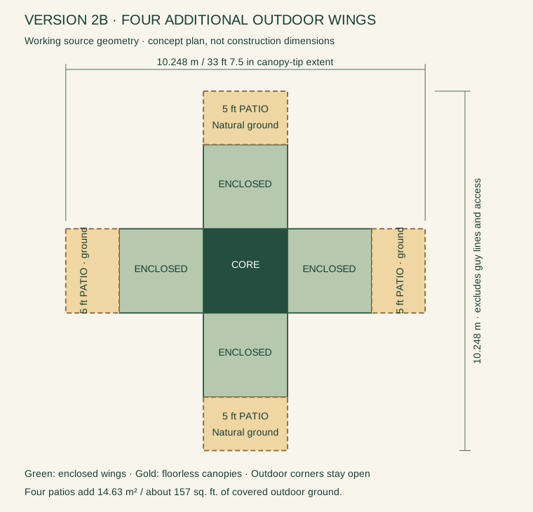
Using the sheet’s 7.2 m square overall layout, the canopy tips span about 10.25 × 10.25 m (33′7½″ × 33′7½″). Allow additional space for anchors, drainage and access. Small steps connect the raised cabin floors to the ground-level patios. Outer poles and anchors support each removable canopy.
A demountable version separates the core, floor panels, ribs and equipment into labelled packages. Take suitable loads along an assessed quad trail with a side-by-side and small trailer, then assemble the cabin at the clearing. This is initial assembly from parts; the cabin’s later fold-up storage is a separate operation.
Per-package design targets only: no component masses have been measured. These are neither whole-cabin weights nor safe manual lifting limits.
The preferred maximum per package, with much lighter pieces wherever practical. Split floor tiles, frame members, wall cassettes and fabric bags.
An exception target for modules that cannot reasonably split further. Plan the actual lifting and handling method around the part.
A trailer-handled option using appropriate ramps, winch or other equipment. This is not a hand-carry target or the whole cabin’s weight.
All weights are design targets, not measured specifications or safe manual lifting limits. Trailer loads and trip count will follow a weighed parts list and the selected vehicle, trailer and route ratings. We’ll develop narrow panels, removable utility modules and separate dry bags for the roof and windows.
IMAGES 11–15 / TRAIL & PATIO
Explore outdoor atmosphere, component kits and an assembly interpretation. The dimensioned diagram above governs the intended four attached five-foot patios; the renderings do not establish that geometry.
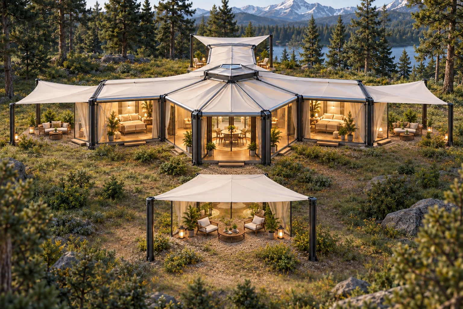
Illustrative patio arrangement: the front canopy is detached and side canopies appear deeper than the intended five feet. A fourth patio is not clearly demonstrated. Visible patios have natural-ground floors; this is an atmosphere study, not the intended arrangement. The dimensioned plan governs four attached five-foot extensions.
Save image 11 ↓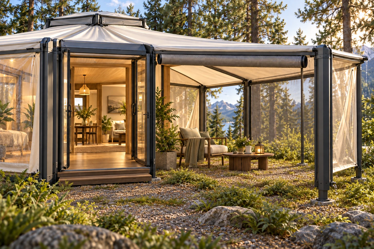
An open-sided, floorless canopy with steps down from the cabin and optional mesh. Its drawn depth is not to scale; the intended extension is five feet.
Save image 12 ↓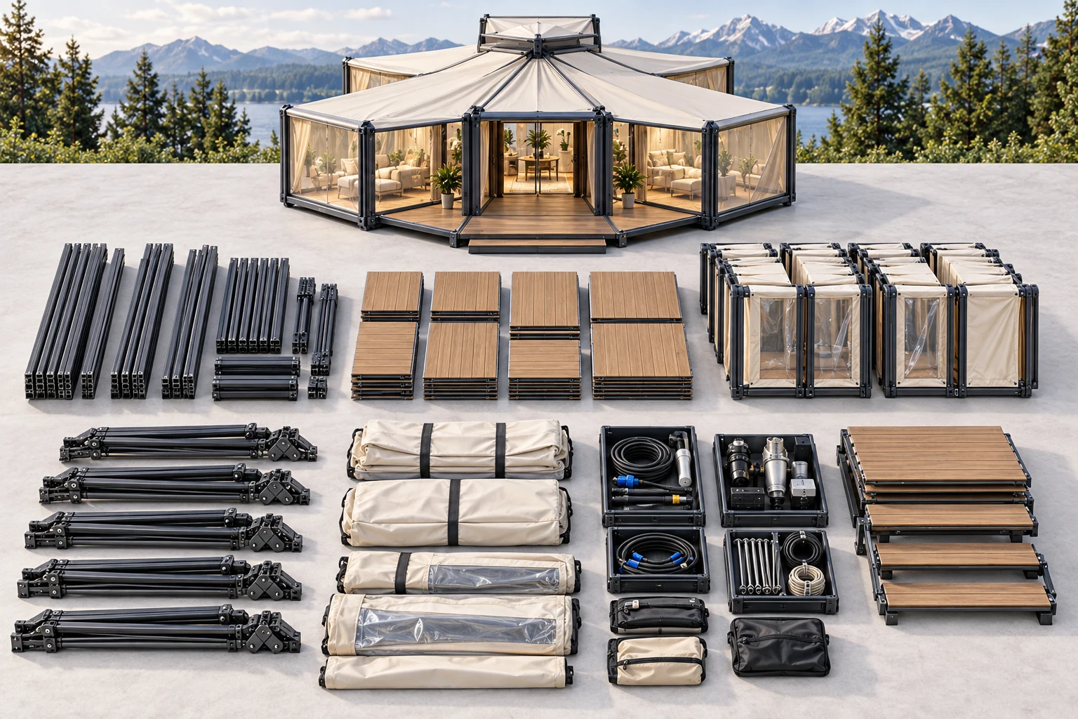
Proposed frame members, floor sections, wall panels, fabric bags and utility modules. Actual packed weights must be measured. The background reads as an octagonal pavilion; the four-wing cross plan governs.
Save image 13 ↓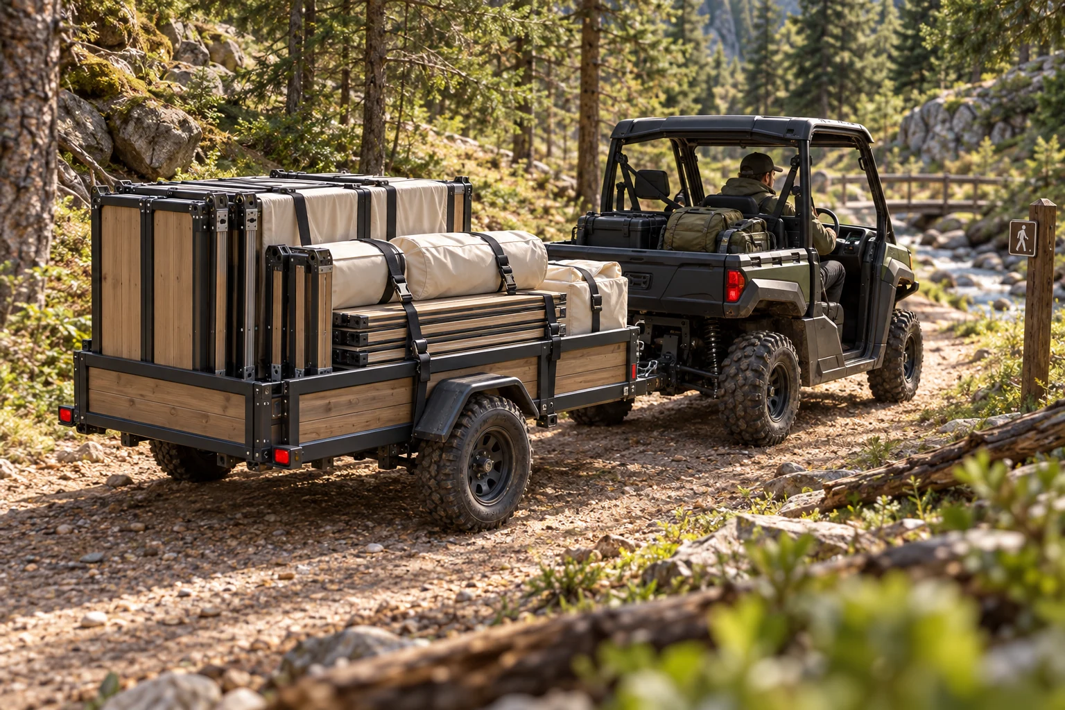
An illustrative single load, not the whole cabin in one trip. Real delivery is expected to need multiple trips and a trailer selected by its verified rating, not its appearance. Vehicle, load restraints and route need to be matched; the pictured sign does not establish vehicle access.
Save image 14 ↓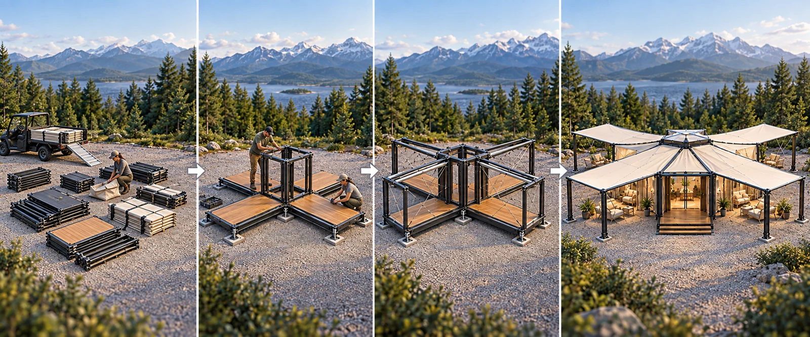
Proposed assembly using small components and a utility vehicle. Panel three simplifies the ribs into straight braced frames; it does not show the articulated mechanism. Roof and canopy geometry differs between panels; the final view is not the exact four-patio plan. Mechanical handling of heavy pieces is not depicted. Trips, component weights and person-hours remain to be measured.
Save image 15 ↓FROM PICTURE TO PRODUCT
First reconcile the footprint. Then build a scale folding model and one full-size wing with real floor layers, ribs, fabric and supports. That prototype will establish the clearances, folding order, drainage and storage space needed before a complete cabin demonstrator.
Promising refinements include guided fabric sleeves, visible rib-lock indicators, individually replaceable window panels and removable seasonal liners. These additions develop the source concept while keeping its four-room pavilion character.
Download the Version 2 study ↓Concept development. Dimensions, capacity, utilities, cost and seasonal performance require their own Version 2 specification. Earlier cabin prices and ratings do not automatically apply.